
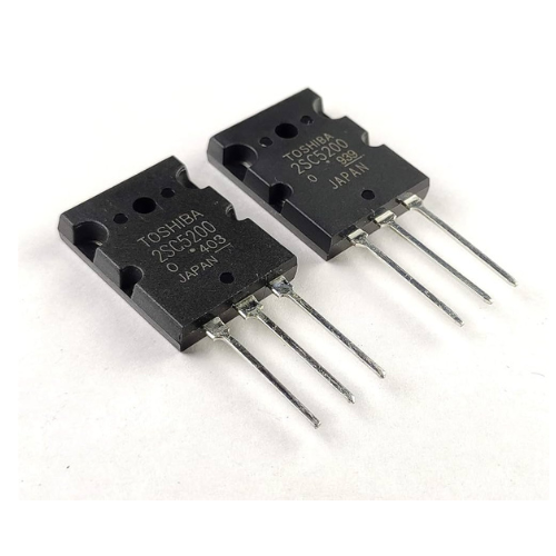
The 2SC5200 is a popular NPN power transistor often used in audio amplifier circuits, power amplifiers, and other high-power applications. If you’re looking to use it in a circuit or understand its functionality, here’s a general guide on how to work with the 2SC5200:
1. Understanding the Transistor’s Pinout:
The 2SC5200 is a 3-pin device, and its pinout is as follows:
- Pin 1 (Emitter): This is the negative terminal, typically connected to the ground or the lower voltage in a circuit.
- Pin 2 (Base): This controls the current flow from the collector to the emitter. It requires a small current to activate the transistor.
- Pin 3 (Collector): This is the positive terminal where the main current flows out.
In a typical NPN transistor, current flows from the collector to the emitter when a base current is applied.
2. Datasheet Information:
When designing circuits with the 2SC5200, refer to its datasheet for key parameters:
- Collector-Emitter Voltage (Vce): 230V (maximum)
- Collector Current (Ic): 15A (maximum)
- Power Dissipation (Pd): 150W (maximum)
- Gain (hFE): 30 to 150 (depending on the specific conditions)
3. Using the 2SC5200 in Circuits:
- Biasing: To switch the transistor on (saturation mode), apply a voltage between the base and emitter (Vbe) of approximately 0.7V. The current through the base (Ib) should be large enough to support the desired collector current (Ic). A typical rule of thumb for the base current is that Ic = β * Ib, where β is the transistor’s current gain.
- Protection: Since power transistors like the 2SC5200 are sensitive to heat and excessive current, it’s important to use a heat sink and ensure proper thermal management to avoid thermal runaway. Additionally, use current-limiting resistors in the base to prevent overdriving the transistor.
- Amplification: In an amplifier circuit, the 2SC5200 typically works in the output stage to drive large currents to the load, while a smaller transistor handles the signal amplification.
4. Example of a Simple Switching Circuit:
- Circuit Components:
- 2SC5200 transistor
- Resistors (for base current limiting)
- Power supply (voltage matching the application)
- Load (e.g., speaker for audio applications)
- Basic Steps:
- Connect the emitter (Pin 1) to ground.
- Connect the collector (Pin 3) to the positive side of the load (e.g., speaker or other high-power device).
- Connect the other side of the load to the positive voltage rail.
- Add a current-limiting resistor between the base (Pin 2) and the input signal or control voltage.
5. Considerations:
- Thermal Management: Since the 2SC5200 can dissipate significant power, it is often mounted on a heatsink.
- Current Handling: Ensure that the load connected to the collector does not exceed the transistor’s maximum current rating.
- Capacitors and Filters: In amplifier circuits, capacitors are often used to filter the input signal and smooth out power supply noise.
6. Common Applications:
- Audio Power Amplifiers: The 2SC5200 is commonly used in the output stage of audio amplifiers to drive loudspeakers.
- Switching Power Supplies: It can also be used in high-power switching circuits, such as power supplies or motor control applications.
- Class AB Amplifiers: Often used in high-fidelity audio amplifiers to produce high-quality sound reproduction.
Always follow the recommended application guidelines in the datasheet, and ensure that the component is operating within safe limits to prevent damage.
If you have a specific circuit or project in mind, let me know, and I can help with further details!
1 thought on “How To 2SC5200 Transistor”
Leave a Reply
Popular
-
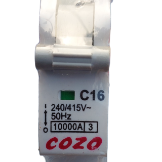 COZO MCB C-16 (1 POLE)
Original price was: ₹320.00.₹200.00Current price is: ₹200.00.
COZO MCB C-16 (1 POLE)
Original price was: ₹320.00.₹200.00Current price is: ₹200.00.
-
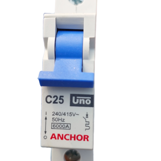 ANCHOR UNO 25A MCB (1 POLE)
Original price was: ₹195.00.₹190.00Current price is: ₹190.00.
ANCHOR UNO 25A MCB (1 POLE)
Original price was: ₹195.00.₹190.00Current price is: ₹190.00.
-
 GREET Room Fan Heater 1000/2000W
Original price was: ₹1,700.00.₹1,250.00Current price is: ₹1,250.00.
GREET Room Fan Heater 1000/2000W
Original price was: ₹1,700.00.₹1,250.00Current price is: ₹1,250.00.
-
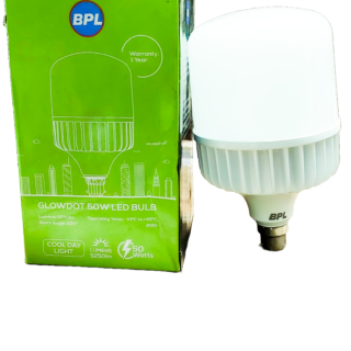 BPL 50 W LED Bulb color White
Original price was: ₹988.00.₹699.00Current price is: ₹699.00.
BPL 50 W LED Bulb color White
Original price was: ₹988.00.₹699.00Current price is: ₹699.00.
-
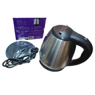 Wyzr Electric Kettle, Capacity: 1.5L Power 1500W
Original price was: ₹1,699.00.₹850.00Current price is: ₹850.00.
Wyzr Electric Kettle, Capacity: 1.5L Power 1500W
Original price was: ₹1,699.00.₹850.00Current price is: ₹850.00.


Hi, this is a comment.
To get started with moderating, editing, and deleting comments, please visit the Comments screen in the dashboard.
Commenter avatars come from Gravatar.